
Last modified on 23rdth January 2003
DISCLAIMER: The information in this page comes with ABSOLUTELY no warranty, or guarantee as to is accuracy, either express or implied. I can in no way be held responsible if you damage your PC by using this device, or for any failure in its operation. Please note that not all serial ports are created equal and some may be unable to operate this device. A good indicator is that if your serial port cannot power a serial mouse then it won't be able to power this circuit either.
Please note that it is a waste of your time contacting me about general NTP issues. These include compiling and configuring NTP. I simply don't have the time to respond to these requests so your email will go unanswered. The correct forum for these questions is the Usenet group comp.protocols.time.ntp
There are a number of low frequency time signals around the world that broadcast accurate time and date information. These signals are used by the many cheap radio controlled wall and desk clocks that can easily be purchased these days. The time signal is also useful for the synchronizing the clocks of computers.
The three best known of these signals are the DCF77 signal broadcast from Mainflingen near Frankfurt in Germany on 77.5kHz which can be received through out most of central and northern europe. The MSF signal broadcast from outside Rugby in England by the National Physical Laboratory at 60kHz which can be received in the anywehere in the British Isles and large parts of northern europe. The WWVB signal is broadcast from Ft. Collins in Colarado by the NIST on 60kHz. This can be received throughout the lower 48 states of the U.S.A. as well as large parts of Canada and Mexico.
All these time signals all work in the same manner. At the start of each second the signal is reduced in strength by between 6 and 10 dB for a varying amout of time before being restored to full power. The length of time the signal is reduced in power is used to indicate a stream of zeros and ones plus some position markers. The exact format of the code varies between each signal but they are all similar in nature.
Unfortunately the off the shelf devices that attaching to a computer for receiving these signals are prohibitively expensive. Presented here is a very simple circuit for interfacing the HKW Electronik OEM modules (or other similar modules) distributed by Galleon in the U.K. and readily available from Maplin, to the serial port of a PC. The total cost of the parts is around £30, is very simple to construct and requires no special alignment or test equipment. There is also some software developed for Linux that will decode the signal and can be used in conjunction with ntpd to keep your PC's clock accurate.
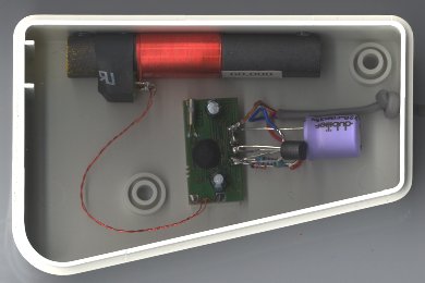
The heart of the device is a EM2S receiver module and matching antenna. The two are matched, so a mixing a 60kHz receiver board suitable for the MSF and WWVB signals with a 77.5kHz antenna and vice versa will not work. It should be noted that the receiver boards know nothing about the format of time signal itself so a 60kHz pair suitable for receiving the MSF signal will also receive the WWVB signal.
When combined they act as complete time code receiver, providing a serial digital data output stream for external decoding. All that is left to do is a means of providing power to the device and interfacing the output stream to the serial port of the computer.
The circuit required to provide the interface is very simple and consists of just four components and a short circuit. A schematic is shown below. The connections on the left are on the receiver board, and those on the right are the serial port on the PC. The pin numbers given are for a 9 pin serial port.
The power for the circuit is derived from the DTR line of the serial port. The serial port can provide around 10mA of current which is more than enough to power the circuit. A small signal diode provides the necessary protection from negative voltages being applied to the circuit when the DTR line is low. The capacitor provides some smoothing and filtering of the power to reduce any noise picked up in the cable being passed to the receiver circuit. The resistor and the transistor provide the necessary interfacing between the open collector output of the receiver board and the serial port. A second transistor is used in emitter follower configuration because the open collector output of the receiver board can only source 2mA, and with the DCD pin of the serial port swallowing 0.5mA, the pullup resistor has a significant voltage drop caused by the current flow into the serial port. On the low voltage serial ports seen on some laptops there is no suitable pullup resistor value that can be chosen. Finally a short is made from ground to PON to keep the receiver in ready mode when power is applied.
The circuit works by toggling the DCD line on the serial port. We are technically abusing the serial port as a one is defined as any voltage above 3V at the receiving end and a zero as any voltage below -3V at the receiving end. However the vast majority of serial ports on PC's interpret a voltage of 0V (or close to) as a zero. The circuit therefore causes the voltage on the DCD line to vary between the DTR voltage (minus 0.6V for the drop over the diode, and another 0.8 for Vce) and GND or 0V. The DCD line can then be polled by the PC to calculate the time the signal spends low and the signal can be stored and decoded. By decoding the signal on the computer rather then a micro-controller the circuit is kept simple and cheap to make.
All the parts are readily available at Maplin, and I have included the Maplin part numbers in the list below, for the bits that I used in making my receiver. The total cost should be just over the £30 mark. You will also need a soldering iron, some wire strippers/cutters, a method of making a hole for the cable in the case and a spare 45 minutes for construction. For readers in the U.S.A. I don't know of any supplier of the receiver boards located in the U.S.A. However the antenna and board sold by Maplin in the U.K. for the MSF signal will work just fine on the WWVB signal and Maplin do ship internationally.
If you wish to build a DCF77 version of the receiver Conrad part number 641138-92 is a combined antenna and receiver module and can be subsituded directly for the MSF parts listed below. As ordering from Conrad is very troublesome for those living in the United Kingdom, with minimum order values, direct bank transfers required etc. I have a number of these modules available for resale at �15 for U.K. residents. Email me for further details.
| MK68Y | 1 × EM2S MSF Receiver module | |
| MK72P | 1 × MSF Antenna | |
| M47K | 1 × 47kW 0.6W 1% Metal Film | |
| DT64U | 1 × 220mF 50V 105° Radial Electrolytic | |
| QQ14Q | 1 × BC547 transistor | |
| QL80B | 1 × 1N4148 Signal Diode | |
| XR20Q | 2 × Lapped Pair | |
| RK61R | 1 × D Range 9 Way Socket | |
| KE94C | 1 × 9 Way Snaplock Hood | |
| LL14Q | 1 × VereoBox 401 |
It should be noted that most of these parts where governed by what I had readily available in my components box. The only parts I specificily purchased for this project where the receiver module and the antenna.
You can use any 1/4W 5% carbon film or better resistor in place of the 0.6W 1% metal film. Any 220mF 16V or better electrolytic capacitor will do. Tantalium capacitors are not suitable as these can generally only survive reverse voltages of less than 0.5V and the diode does not provide sufficient protection. Any small signal silicon NPN transistor should do the job. I just happened to have a BC547 in my box of components. The BC108, 2N2222A and 2N3904 are also known to work.
The enclosure was again something left over from a previous project. A perhaps more suitable and slightly cheaper box would be the Miniature ABS 80x40x17mm plastic box from Hammond Manufacturing (Maplin part no. SC80B). However you can use any small plastic box that will accomadate the components. A metal box should not be used as that would screen the antenna.
If you intend to connect the receiver to a 25 pin serial port then you will need a D Range 25W socket part no. YQ49D, and a 25W Snap lock hood part no. JW91Y instead of the 9 way parts in the above list. You will also need to connect the lead to pins 8,20,7 instead of 1,4,5 respectively.
I have included two metres of cable to connect the device. It is quite a thin cable and you may wish to replace it with Lapped Pair 7/0.2mm part no. XS23A which is a thicker more robust cable. This would be especially wise if you intend to use a longer cable run, particularly as the cable I have used has quite a high capacitance. I have tested the receiver with an extra 2 metres of serial cable extension in and it still worked for me. However your mileage may vary. If you do intend to use a long cable run then a low capacitance cable such as Twin Mic Cable (Maplin part no. XR08J) or Shark Common Pair (Maplin part no. XS04T) would be advisable.
To keep things simple, and as we only have four components the circuit is realized by soldering the components directly to the receiver board. This point to point construction style is extremely reliable and saves the hassle of using stripboard or making a PCB. Construction can be fiddly as the receiver board is only 25x13mm in size. A spare pair of hands or one of those "helping hand" devices is recommended though not necessary. It is also advisable to undertake ESD precautions when handling the receiver board. A wrist band and a low leakage soldering iron are probably sufficient protection. The notes are for the MSF/WWVB receiver from Maplin, see below for differences for the DCF77 receiver from Conrad.
If you are using the DCF77 receiver board from Conrad as mentioned above things are slightly different. Firstly there is no need for the short as the board is always in receive mode. Secondly the antenna comes pre-attached to the receiver. Thirdly the connections to the receiver are made via screw down terminals so you only need two solder joints inside the case and three in the serial port if you attach the diode to the receiver. Finally you need to connect the base of the transistor and the pull up transistor to termial 4 on the receiver. It is the one maked inverted. Though I believe this is incorrect labelling.
The software that is provided can be run in two modes. By default it detaches itself from the terminal and runs in the background sending the time signal to the ntpd daemon via the shared memory reference clock driver every minute. In the other mode which is useful for testing, the decoded pulses and time are printed to stdout.
The one program covers the DCF77, MSF and WWVB time signals. The time signal being received is automatically determined from decoded pulses. The program also takes as its last option the serial port device the clock receiver is attached to. For more information consult the included man page.
Testing mode is selected by specifying the -t command line option. All other command line options are the same as for normal usage. In the testing mode the received time is not sent to the ntpd daemon.
You will probably have to recompile the ntp software yourself as the version included in most Linux distributions does not include the shared memory reference clock driver. I suspect this is because when running configure, specifying --enable-all-clocks and --enable-parse-clocks is not sufficient to include the shared memory reference clock driver. You need to specify --enable-SHM when running configure to have the shared memory reference clock driver included. You probably want to do this anyway and replace the existing refclock_shm.c from the ntp distribution with the one in the radioclkd tarball. This version supports the extra setting flag3 1 for the SHM reference clock. This stops ntpd from making excessive entries in the system logs if no new timestamp can be found in the shared memory segment. This happens for example if the transmitter goes off air for some reason.
The software can be downloaded from the link below. Apart from the TIOCMIWAIT ioctl the software is ANSI C/POSIX complient and should be easy to modify to run under other Unix varients. Any patches for this would be welcome. It should also be noted that the WWVB code is also untested in the field, though it has undergone extensive simulated testing and I believe it to be functioning correctly. However it would be prudent to procede with caution while using this mode, until correct operation is reported.
If you have problems getting the software to work, try the command stty crtscts < /dev/ttyS0 where ttyS0 is the serial port the receiver is connected to. You may also want to try running watch -n 1 cat /proc/interrutps. If the number of interrupts on the serial port is not steadly increasing then there is a problem with the serial port detecting interrupts. As a last resort you may specify a -p command line option, in which case the program will poll the serial port every 10ms. This uses slightly more CPU time and is not quite as accurate.
When siting the receiver module, it is important to keep it away from metal objects and as far as possible from any electronic equipment. I have mine BlueTac'ed to the underside of a shelf. Though if I move it six inches to the right so it is tucked behind a shelf bracket it generates lots of errors. When aligning the unit, for maximum signal strength it needs to be placed at right angles to a line from the location of the antenna to the transmitter you are trying to receive.
It should also be noted that during normal use you will occasionally see errors in the received signal. All it takes is a bit of noise at 60kHz or 77.5kHz while the signal is in the low state which in turn introduces a spurious return to the high state and as a result generates an error. In the event of an error while trying to decode the time signal the daemon aborts the current decoding and starts again from scratch.
Due to delays in the propogation of the radio signal, it's processing by the receiver board and the latency of the operating system the time decoded by the receiver will be slightly slow of actual UTC. Typically this delay will be less than 20ms, so unless you are very fussy about the time, or are using more than one time source, such as a GPS unit, other radio clock or NTP server on the internet you can ignore this section.
The basics of the calibration procedure is to determine the average offset of the radio receiver, and use the time1 fudge factor in ntp.conf to bring the receiver as close as possible to the real time.
The easiest way of determining the offset of the radio receivers time is to run it against a reference clock that does not suffer from these problems. The best reference clock would be a GPS unit. This might be a GPS unit that you don't wish to dedicate to time keeping, or a borrowed unit. If this is not possible you could use a stratum 1 server on the internet.
The method of calibration is quite simple. We attach the calibration reference clock to the computer and fudge the stratum of our radio receiver up to say 5. This way we can be sure that ntpd will lock onto the calibration reference clock. We need to make sure that ntpd is configured to collect peer statistics so make sure we have some lines similar to these in ntp.conf
    statsdir /var/log/ntpstats/
    statistics loopstats peerstats clockstats
    filegen peerstats file peerstats type day enable
After that we restart ntpd and leave it running for several hours. We can then make a copy the peerstats file. The trick is to remove all the entries before ntpd has come into close aggrement with the calibration reference clock and then run the peer.awk script in the scripts/stats directory of the ntp distribution. This will give us a mean offset of our radio receivers in milliseconds. This can them be converted into seconds and added to the fudge line in ntp.conf for our receiver.
The final step is to remove the change in stratum level for our reference clock and restart ntpd. If you move the receiver any significant distance then you will need to repeat this calibration step. Across the room or around the current building will be fine, but if you move it to the next town/city then you will need to recalibrate.
You can attach two different receivers to the same serial port. This is most useful in those parts of northern europe that can receive both the DCF77 and MSF signals. This provides an element of redundancy in case one transmitter is off air. When combined with a GPS unit this provides a very inexpensive backup of the GPS signal. If you wish to attach a second unit to the system you much attach the power line to the RTS pin, and the signal line to the CTS pin. These are pins 7 and 8 respectively on a 9 pin serial port. On a 25 pin serial port they are pins 4 and 5 respectively.
The software will automatically determine whether two receivers are attached, and what signal is on which one. The second receiver, i.e. the one attached to the CTS pin will appear to ntpd as the reference clock 127.127.28.1